NORTH SAILS DESIGNS INVENTORY FOR NEW MELGES IC37 CLASS
Designer Mike Marshall explains 3Di sail development
From northsails.com
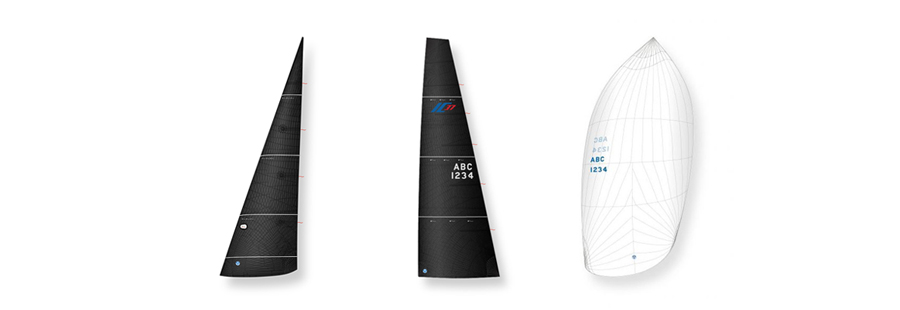
When notified that North Sails would be the official sailmaker for the Melges IC37 class, the design team realized we had a challenging task before us. An inventory of only three sails – one main, one jib, and one spinnaker – and only one standing rigging tuning adjustment allowed during class regattas (the mast ram). Given these requirements, how could we design a set of sails to cover the entire wind range when racing this 37-foot one-design boat? Fortunately, we had all the tools we needed with North’s 3Di technology and the North Design Suite of modeling software.

It was clear from the outset that 3Di was the only option for sails that could take the loads of a 37-foot boat yet perform well in winds anywhere from 5 to 25 knots. With 3Di, tapes are oriented in the direction of the loadings, giving outstanding stretch resistance, and Aramid and Dyneema fibers provide exceptional durability. So the 3Di decision was an easy one.
Next we got to work perfecting sail shape through aero-elastic modeling. In a seven-step process passed down from years of America’s Cup development, the Melges IC37 sails were modeled in a variety of wind conditions. Thanks to a close relationship with Southern Spars we had access to very detailed mast information, such as mechanical properties and rigging attachment points, which allowed us to design sails that would perfectly fit the mast of the Melges IC37.
Here are the seven steps in the sail development process:
Step 1: Build a model of the rig. Using North’s Desman program, we created a complete three-dimensional model of the spars and rigging.
Step 2: Determine the base rig tune of the mast. Through our partnership with Southern Spars, we obtained the maximum loaded tuning and rigging specifications for the Melges IC37 and ran it through the program Membrain, to determine the maximum and minimum mast bend from tuning. This, in turn, provided the minimum and maximum mast ram positions and the range of mast bends and headstay sags the sails would see up the wind range. .
Step 3: Design the sails and place them on the rig. Using the program Spiral, we specified a shape for each sail. This software defines a sail’s three-dimensional shape as a “molded” surface without any wind pressure or load applied.
Step 4: Define the structure of the sails. Using the software module Warps, we selected 3Di construction and created the taping layout of the sails. The structure of a sail is as important as its designed shape, because these two factors must work together to achieve the sail’s “flying shape.”
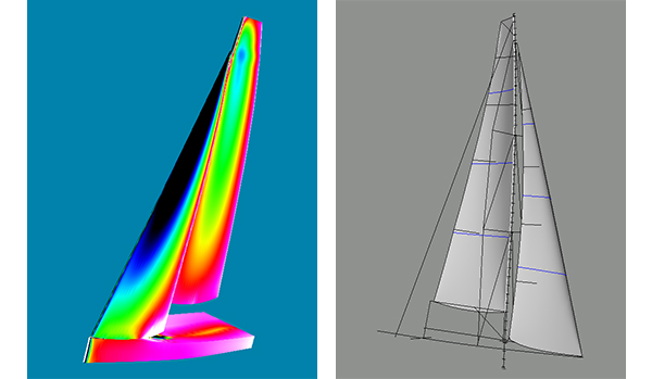
Step 5: (left) Apply wind pressure to the sails and rig. We used the program Flow to introduce wind pressure over each sail’s three-dimensional mold and produce a pressure map on the sail’s surface. This pressure field was then linked to the program Membrain, to see what effects wind pressure would have on the molded sail shape.
Step 6: (right) Apply a pressure map to the molded sail shape. Using Membrain , we took the rig and sail model developed in the first four steps and applied the pressure field from Step 5. Membrain considers the specific properties of the sail’s construction, adds in wind pressure, and shows how the sails will deform (stretch) when they are loaded.
Step 7: Carry out aero-elastic coupling. Once a sail’s flying shape is tuned and trimmed in Membrain, the deformed (pressurized) shape is sent back to Flow. This shape is different than the molded shape created in Spiral (without any wind pressure), so Flow recalculates a pressure map, which is then sent back to Membrain and applied to the sail to get a new deformed shape. This process is called aero-elastic coupling. Within the North Design Suite, the computer keeps going back and forth between Flow and Membrain until there is little or no additional change in Membrain’s deformed sail shape. At this point, we know that the sail shape is in balance with the wind loads on the sail.
After carefully considering multiple design options and running many load cases, we developed a set of sails for the Melges IC37 that would optimally fit the range of mast bends and perform well from 5 knots of breeze all the way up to 25 knots. We also determined the tuning for the mast, all before the first boat even left the mold.
North’s 3Di technology and North Design Suite go hand-in-hand and we are excited to see our work come to life when Hull #1 hits the water in a few weeks. What goes on behind the curtain tends to go unnoticed, but with the new launch on the horizon, our designers are proud to introduce to you the new North-powered Melges IC37 Class, the newest addition to Corinthian one design competition, with industry-leading technology that sailboat owners and crew will love.
Find out more on the Melges IC37, or speak with your local expert today.
 and then